65+ network symbols
Network equipment, industrial automation & OT, servers & IT, infrastructure, plus zones and groups.
Network topology diagram software
Map network devices, connections and communication paths in a straightforward editor built for technical documentation — from everyday IT networks to industrial Ethernet and OT architecture.
Place switches, firewalls, PLCs and SCADA servers, connect them port to port, and keep cable, IP and VLAN information on the objects instead of in loose text.
No installation · No account to try · PDF · SVG · DWG
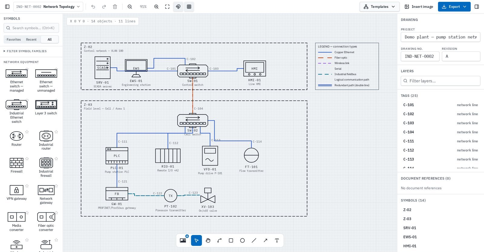
Generic diagram tools leave you aligning lines by hand. In InduDraft, links belong to the devices they connect, so the drawing stays tidy when the network changes.
Start from Industrial Ethernet, Basic IT, Redundant ring or IT/OT architecture — or start blank.
Search the Network & Communication library and place devices on the canvas.
Drag from a device port to another device. Choose copper, fiber, wireless, serial, fieldbus or logical path.
Add device names, IPs, VLANs and cable IDs, then export PDF, SVG or DWG.
Network equipment, industrial automation & OT, servers & IT, infrastructure, plus zones and groups.
Links attach to ports, follow devices when moved and route orthogonally. Several links per device.
Copper, fiber, wireless, serial, fieldbus, logical path and redundant links — by pattern, not colour alone.
Device name, manufacturer, model, IP and MAC address, subnet, VLAN, location, rack and interfaces.
Cable ID, ports, cable type, speed, protocol, VLAN and length. Duplicate cable IDs and IP addresses are flagged.
Security zones, DMZ, subnets, VLANs and site containers to show network boundaries.
Draw the physical network with switches, cables and ports — or a logical architecture with zones, firewalls and communication paths. Logical paths have their own line style so they are never confused with cables.
A network diagram is only useful if it is correct and easy to update.
PROFINET or EtherNet/IP networks from SCADA and HMI down to PLCs, remote I/O and drives.
Document enterprise, DMZ, operations and control zones and the conduits between them.
Show MRP rings and redundant paths clearly for commissioning and maintenance.
Deliver clear network drawings with packaged systems and keep them updated.
Network topology icons are not defined by a single graphic symbol standard. InduDraft uses its own vendor-neutral symbols and supports documenting concepts from these references.
InduDraft is not certified or endorsed by any standards organisation, and drawings are not validated for compliance.
DWG export produces editable 2D CAD geometry, not intelligent network objects.
A network topology diagram shows the devices in a network and how they are connected — physically (cables, ports, fiber) or logically (subnets, VLANs, zones and communication paths).
Yes. The Network & Communication library includes industrial switches, routers and firewalls, PLCs, safety PLCs, remote I/O, RTUs, DCS controllers, HMIs, SCADA and historian servers, gateways, drives and networked field devices.
Connections attach to device ports and stay attached when you move equipment. Each link stores its connection type, cable ID, ports, cable type, speed, protocol, VLAN and length as structured data.
You can draw labelled security zones, place equipment inside them and draw conduits as labelled logical paths, following the IEC 62443-3-2 zone and conduit concept. InduDraft does not calculate security levels or verify compliance — the diagram is documentation.
Yes. Mark any link as a redundant path (shown as a double line) and label the protocol, e.g. MRP, PRP or HSR. InduDraft documents the design; it does not simulate the protocol.
Not yet. Automatic discovery, LLDP/SNMP import and config-based generation are not available. Diagrams are drawn and edited in the editor.
Yes. DWG export works today for signed-in users. It produces editable 2D CAD geometry, not intelligent network objects. DWG is planned as a Pro feature after the preview period.
Yes. Open the network editor in your browser without creating an account.
Also drawing process, electrical or cabinet drawings? See P&ID software, single-line diagram software and GA drawing software.
Open the editor with an industrial Ethernet example. No installation and no account required to try.